Dream-UMI:
Build and Calibration
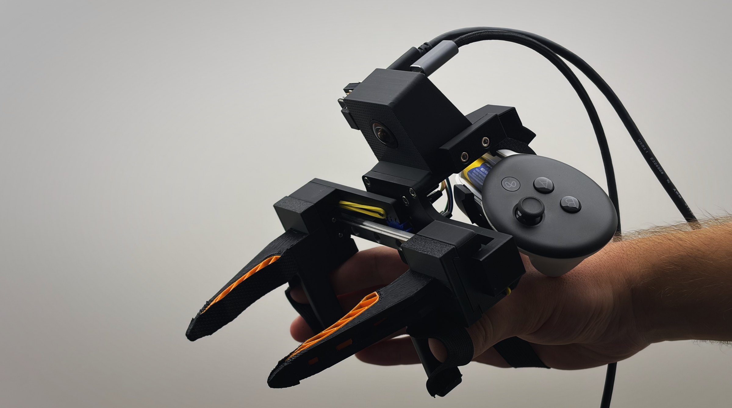
For my bachelor thesis at ETH Zurich, I am developing a UMI1Chi et al. (2024). Universal Manipulation Interface: In-The-Wild Robot Teaching Without In-The-Wild Robots. arXiv:2402.10329. device with Dream Machines for the TRLC-DK12The Robot Learning Company. TRLC-DK1 documentation. robot arm. Dream Machines builds robotic AI that learns from demonstration and experience, letting manufacturers automate repetitive work on their own and without custom machinery.
Currently, we collect data using tele-operation. This means every person collecting data needs a robot arm, which doesn’t scale. Plus, fine motor tasks like opening zip-lock bags, handling zip-ties, or sorting screws are a pain in the ass. That is where UMI comes in: a handheld copy of a robot’s gripper used to solve the task directly, while its camera and sensors record data to later train the robot. But will it replace tele-op entirely? Tele-op data comes from the real robot and matches it exactly, while UMI data comes from a human hand and never quite does. The current idea is to use it for pre-training and then fine-tune the policy using tele-op data.
I’ve just hit my first milestone: a capture-ready UMI device. In this blog post, I’ll share the development journey and the reasoning behind major design decisions.
- Milestone 1reachedCapture-ready deviceCamera and encoder streaming via USB, the Quest streaming over Wi-Fi. Device calibrated.
- Milestone 2Operator-friendly collection systemBimanual (one gripper in each hand) mobile setup with user input and feedback, and a robust post-processing pipeline for high-fidelity UMI data.
- Milestone 3UMI data in trainingInvestigate how UMI data can be integrated into the current training process.
Research Papers
Hardware-wise, papers mainly differ in these three questions:
- How do you track the pose? With SLAM3Simple AI et al. (2026). HiFi-UMI: Learning Deployable Manipulation Policies from High-Fidelity UMI Data Alone. arXiv:2607.25895., a VR headset4Ohkawa et al. (2026). YUBI: Yielding Universal Bidigital Interface for Bimanual Dexterous Manipulation at Scale. arXiv:2606.10244., or external motion capture5Zhang et al. (2026). Hy-Embodied-0.5-VLA: From Vision-Language-Action Models to a Real-World Robot Learning Stack. arXiv:2606.14409.6Helmut et al. (2025). Tactile-Conditioned Diffusion Policy for Force-Aware Robotic Manipulation. arXiv:2510.13324..
- How do you track the gripper width? With ArUco tags6Helmut et al. (2025). Tactile-Conditioned Diffusion Policy for Force-Aware Robotic Manipulation. arXiv:2510.13324. or a rotary encoder3Simple AI et al. (2026). HiFi-UMI: Learning Deployable Manipulation Policies from High-Fidelity UMI Data Alone. arXiv:2607.25895.4Ohkawa et al. (2026). YUBI: Yielding Universal Bidigital Interface for Bimanual Dexterous Manipulation at Scale. arXiv:2606.10244.5Zhang et al. (2026). Hy-Embodied-0.5-VLA: From Vision-Language-Action Models to a Real-World Robot Learning Stack. arXiv:2606.14409..
- Is the setup mobile3Simple AI et al. (2026). HiFi-UMI: Learning Deployable Manipulation Policies from High-Fidelity UMI Data Alone. arXiv:2607.25895.4Ohkawa et al. (2026). YUBI: Yielding Universal Bidigital Interface for Bimanual Dexterous Manipulation at Scale. arXiv:2606.10244. or stationary5Zhang et al. (2026). Hy-Embodied-0.5-VLA: From Vision-Language-Action Models to a Real-World Robot Learning Stack. arXiv:2606.14409.6Helmut et al. (2025). Tactile-Conditioned Diffusion Policy for Force-Aware Robotic Manipulation. arXiv:2510.13324.?
I have adapted YUBI’s4Ohkawa et al. (2026). YUBI: Yielding Universal Bidigital Interface for Bimanual Dexterous Manipulation at Scale. arXiv:2606.10244. approach with a Meta Quest, magnetic encoder and mobile setup.
Hardware
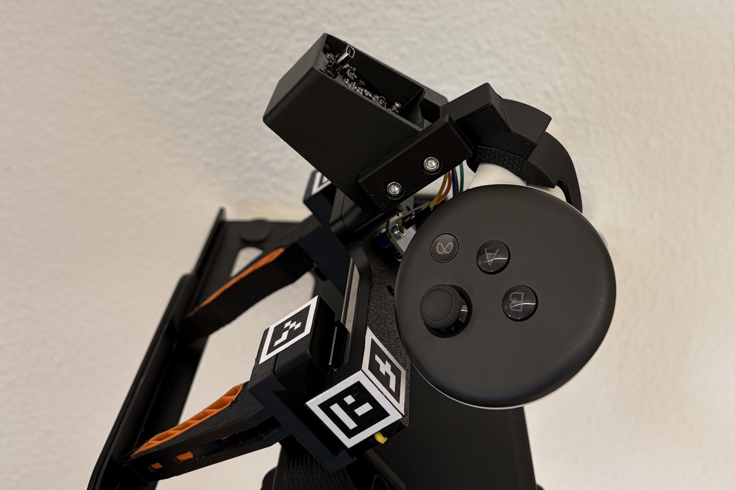
To minimize the embodiment gap, the UMI’s camera view should match the robot’s. Below are the 3D models of both the robot’s end-effector and my UMI gripper. I’ve highlighted the key design changes in the exploded view.
Naturally, every part went through multiple iterations during development. I’d like to showcase four of these early prototypes, three of which are highlighted in the 3D model below.
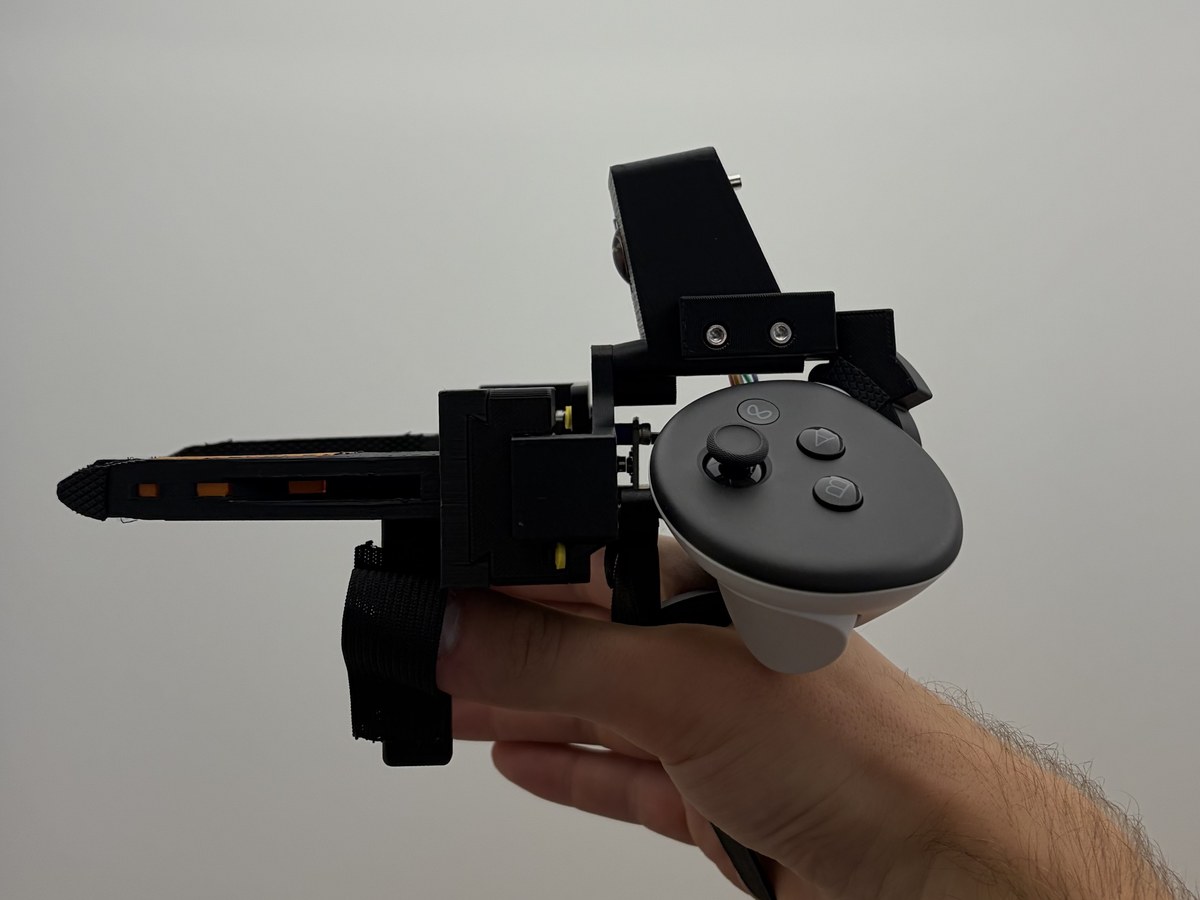
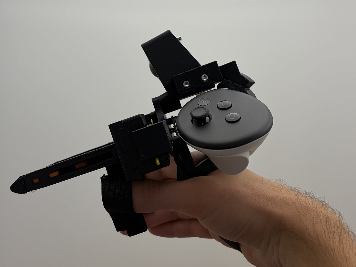
- Controller mount. The previous layout caused an uncomfortably high moment of inertia during operation, but the new version handles much better. A potential future refinement could be moving the controller even closer to the wrist (the center of rotation) to see if that improves handling further.
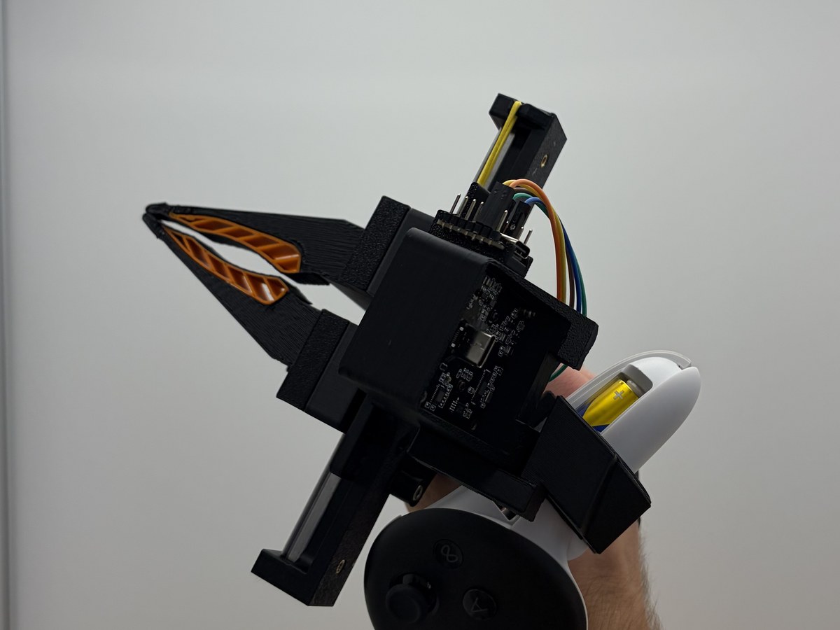
- Finger shaft position. Moving the fingers closer to the jaw tips allows for much finer control. However, this puts the fingers in the camera’s view, and I still need to test whether this impacts data quality.
- Hand rest. While YUBI uses a grip, I prefer Generalist AI’s hand strap approach. The first iteration tried to cover the sharp edge but was still uncomfortable to wear. Ergonomics remains a major open challenge, as there is no analytical solution to human comfort.
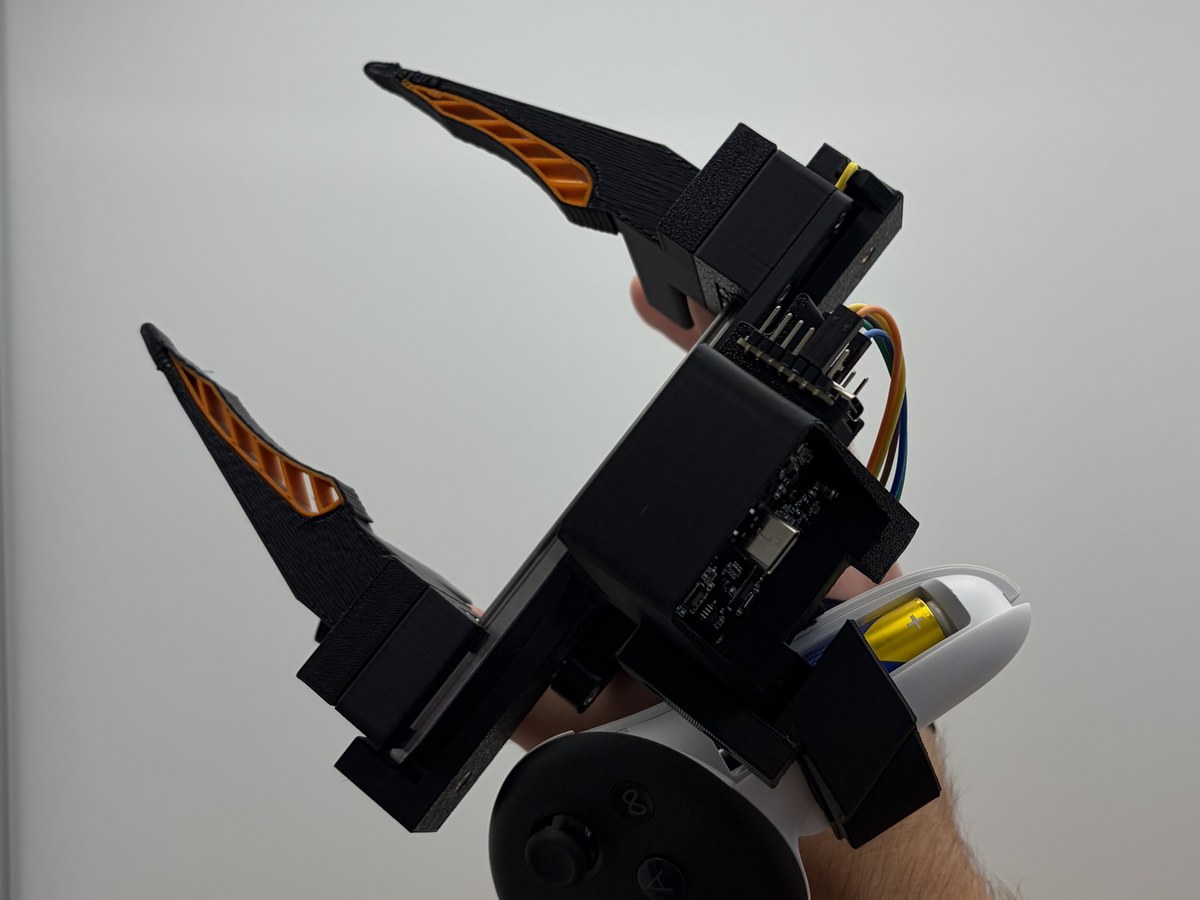
- Rubber bands. The bands themselves aren’t in the model, but you can see the attachment hooks. Originally, a single one routed behind the mount, inspired by YUBI. This caused a major issue with the force angle: when fully open, it pulled almost perpendicularly and barely helped. It also got in the way of the magnetic encoder. The new version routes the bands straight, fixing the pull angle. Rubber bands also wear out after some use, but the straight routing allows an upgrade to a steel spring later on.
Ergonomics
A couple of design decisions improved the handling comfort of the UMI gripper:
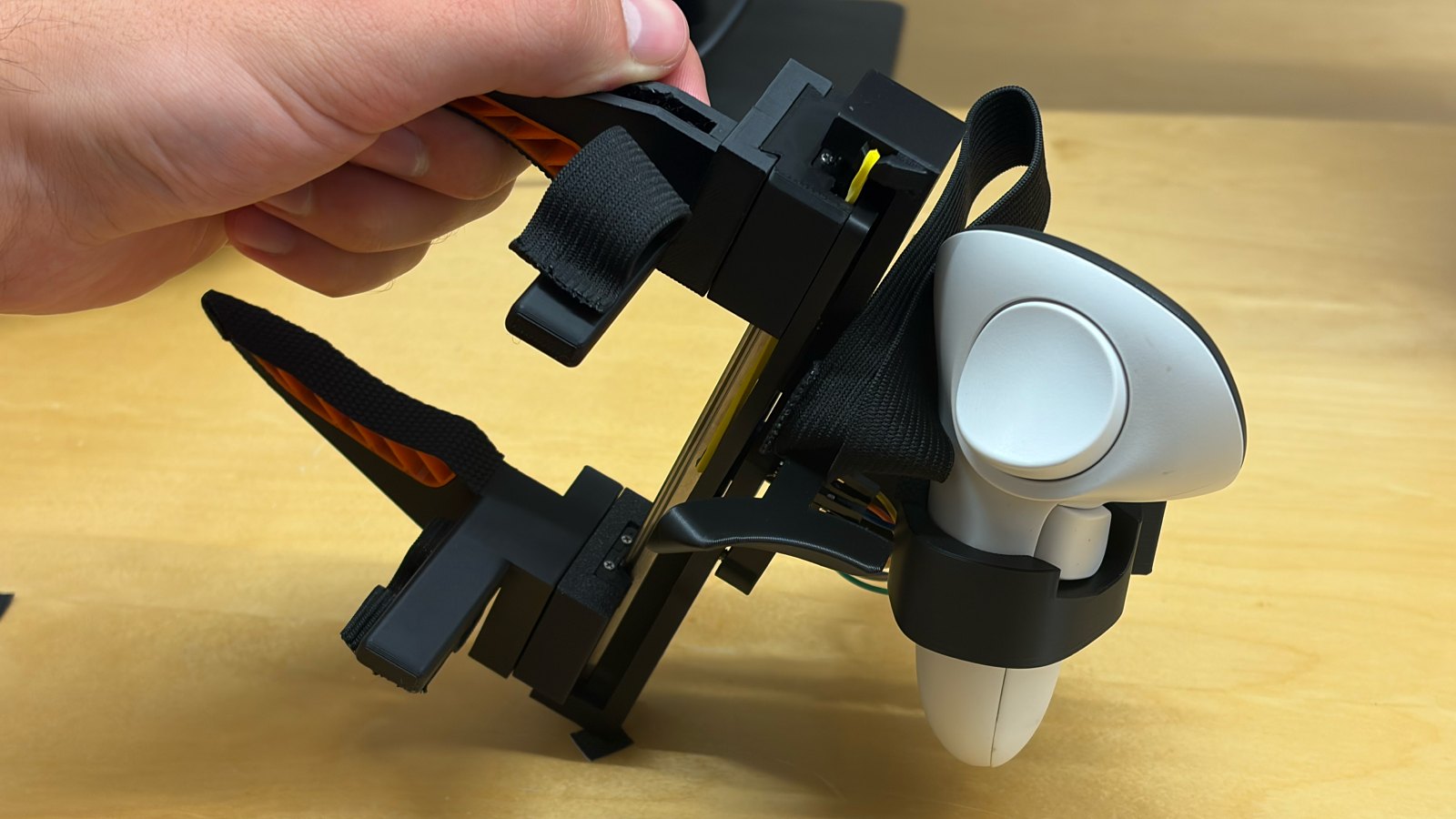
- Finger sleeves. These are essential for controlling the gripper’s rotation when not using a traditional grip.
- Rubber bands. Manually opening the parallel jaws can be strenuous, especially for smaller hands. The bands keep the jaws open by default, while the effort needed to close them remains negligible.
- Quest mount. The controller is heavy. Where it sits completely defines the device’s balance and moment of inertia.
- Hand rest. The toughest piece to get right, since comfort is subjective. It sits off-center and a bit lower than expected. This positioning is necessary for finger clearance, but it also naturally encourages an overhead approach, which is better for the robot.
Outlook
Looking ahead, there are a few open questions and potential refinements for future iterations of this setup:
Grip vs. hand strap: After 3D-printing and testing out the YUBI gripper, I’ve decided against using a grip for this build. However, I haven’t done a direct comparison for my specific parallel-jaw setup, so the debate remains unsettled.
Collection controls: Holding a UMI gripper in each hand leaves no fingers free to press control buttons and foot pedals would make the setup less mobile. Definitely something I’ll need to solve. YUBI’s workaround involves triggering recordings via a fast double-clicking jaw motion. System feedback also needs to be re-routed since the operator won’t be staring at a screen. Haptic feedback or LEDs might do the job.
Involuntary wrist rotation: When closing the parallel jaw, your wrist naturally rotates slightly, which doesn’t happen with rotary grippers. If the operator doesn’t subconsciously correct for this, the recorded data will teach the robot to shift its arm joints just to close its gripper. Might be fixed by tweaking the hand rest.
Human intuition vs IK solver: Standard 6-DOF IK solvers feel unnatural for free floating controllers. Aurel Arnold wrote about it in his blog post (see: Control that feels natural) and solved this by decoupling wrist position from gripper orientation, a solution I would like to adapt. However, the human wrist isn’t located where the robot’s wrist joint is. This physical offset might not matter for relative motion in tele-op, but it could cause issues when reconstructing the absolute pose in a world frame.
Jaw Position Reading
The original UMI reads the jaw position visually using ArUco tags. While this requires no extra hardware, the tracking is less reliable than a physical encoder, which is why most setups nowadays use the latter. I wanted to see exactly how they stack up against each other, so I put them to the test. My trial included calibration at known jaw widths, a minute of natural object grasping, fast jaw sweeps, and a low-light run.
AS5600 magnetic encoder vs ArUco tags
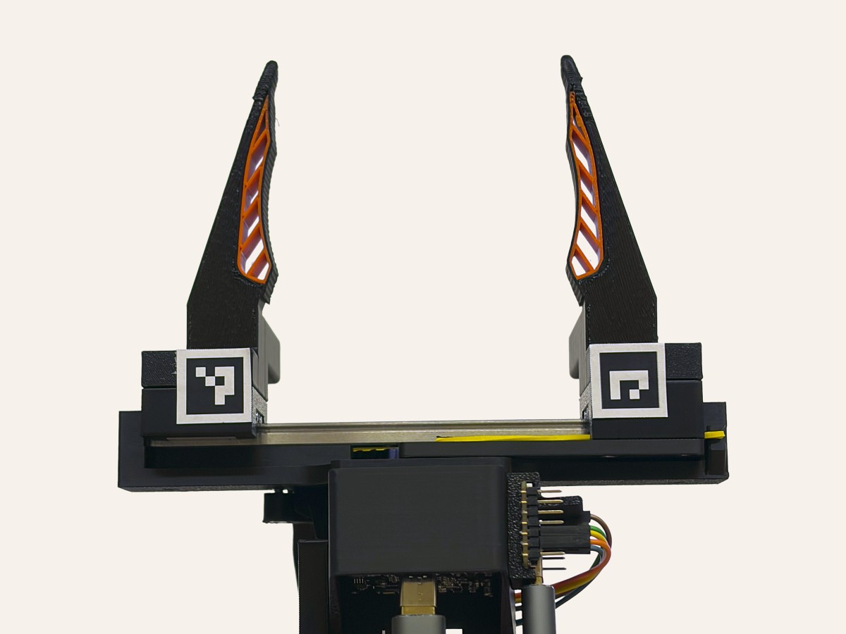
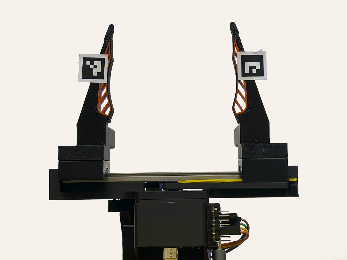
ArUco tag placement
I tested two placements of 15mm ArUco tags (Figure 1). The closer one (left) is a little out of focus, but it performs very well. Moving the tags into focus makes the viewing angle steep and the tags smaller, so tracking actually gets less reliable. If a tag isn’t perfectly flat, which thin paper isn’t, the readings get even worse at that angle.
Calibration
I started with a simple calibration: read the fully open and the fully closed position and interpolate linearly in between. Closed here means the jaws barely touch, so they don’t deflect at all. For the advanced calibration, I set calipers to known widths from 10mm to 80mm in 10mm steps, closed the UMI on them and fitted a model to the readings. I did this for the encoder and for two tag readings: the 3D distance between the tags, which needs the camera model, and their plain pixel distance, which doesn’t. For each of them I tried a straight line, a quadratic and a cubic. For the encoder and the 3D distance a straight line suffices, while you need a cubic for the pixel distance.
| RMSE | bias | |
|---|---|---|
| Encoder | ||
| simple | 0.32mm | −0.26mm |
| advanced | 0.21mm | −0.07mm |
| Tags, 3D distance | ||
| simple | 0.32mm | −0.26mm |
| advanced | 0.20mm | −0.05mm |
| Tags, pixel distance | ||
| simple | 6.62mm | +5.99mm |
| advanced | 0.18mm | −0.02mm |
| simple: RMSE | bias | advanced: RMSE | bias | |
|---|---|---|---|---|
| Encoder | 0.32mm | −0.26mm | 0.21mm | −0.07mm |
| Tags, 3D distance | 0.32mm | −0.26mm | 0.20mm | −0.05mm |
| Tags, pixel distance | 6.62mm | +5.99mm | 0.18mm | −0.02mm |
Advanced model: a straight line for the encoder and the 3D distance, a cubic for the pixel distance.
With the advanced calibration, the pixel distance is as good as the 3D distance, so no camera model is needed. I will use the pixel distance to evaluate results.
Any error below 0.5mm is essentially meaningless, as I couldn’t have positioned the jaws by hand more accurately than that. When I close the jaws on the calipers by hand, the rubber grip tape giving way or the jaws flexing alone leads to bigger errors than that.
Results
The key figures are tag reading minus encoder reading, with the pixel distance and the advanced calibration.
| bias ± SD | 95% of frames | tags seen | |
|---|---|---|---|
| Natural grasping | +0.04 ± 0.46mm | −0.78 … +1.03mm | 90% |
| With fast jaw sweeps | +0.06 ± 0.61mm | −1.00 … +1.48mm | 80% |
| Low light | +0.10 ± 0.75mm | −1.30 … +2.35mm | 29% |
Breaking down the results from the trial, a few key things stand out:
- Agreement: In the 1,798 frames where both tags are visible, 95% of readings fall between −0.78 and +1.03mm of the encoder (Figure 2). On average the tags read just 0.04mm higher, so there is no constant bias.
- Camera lag: Images arrive at the host 45ms later than the encoder data. That’s the shift at which the tag and encoder readings of the motion trials agree best. I corrected for this lag across all results.
- Jitter: The encoder is incredibly stable (at most 0.01mm of frame-to-frame jitter). Held still, the ArUco tags jitter by 0.05 to 0.13mm, performing worst when the jaws are wide open. In motion, their jitter grows with jaw speed, to about 0.3mm at 1str/s and 0.4mm above 1.5str/s.
The main weakness of visual tracking is frames where the tags aren’t detected at all. During 66 seconds of natural object grasping, 10% of all frames gave no reading. These dropouts happen most frequently during fast jaw motions. To see how far that goes, I added deliberately fast jaw sweeps to the trial (see Figure 3): below 0.5 strokes per second the tags read in every frame, above 2 strokes per second only in 9%.
Conclusion
While a 1mm error margin and a 90% reading success rate can certainly be improved, visual tracking will never match the raw precision of a physical encoder. On the other hand, the encoder comes with a lot of extra hardware (rack and pinion, bearing, magnet, AS5600, cables, ESP32, USB-C cable) and is an additional data stream to handle. But once installed, the readings are spot-on.
Verdict: Go with the encoder.
Lessons from the AS5600
The AS5600 encoder came with a tiny magnet (4mm diameter, 2mm thick). Initially, I struggled with periodic signal jumps, noise, and interference from other magnets. I solved all of this by simply moving the magnet closer to the chip, currently sitting at under 0.5mm. The datasheet specifies a distance of 0.5–3mm, but my magnet is likely on the small and weak end, so I had to get as close as possible. A stronger magnet would sit further away.
The chip reports an Automatic Gain Control (AGC) register, ranging from 0–128 at 3.3V, indicating how much the signal is amplified. My readings are between 3 and 11 depending on the orientation. This means I shouldn’t move any closer (which I physically can’t) and that there is a slight but negligible asymmetry, likely from an off-center positioning.
A quick tip on rotation span: My pinion rotates about 260°. If your mechanism spins more than 360°, you’ll have to handle the 12-bit rollover from 4095 back to 0 in software. Best to avoid that altogether.
Quest App
Following the approach of YUBI, I built a custom Quest app in Unity to read the controller poses.
Here is the process:
- Download Unity Hub. In it, install Unity 6.3 LTS with Android Build Support (OpenJDK, Android SDK & NDK)
- Add the Meta XR All-in-One SDK from the Asset Store through the Package Manager inside Unity. Switch build platform to Android and run Meta’s Project Setup Tool.
- Create a Meta developer account, turn on developer mode in the Meta horizon phone app, connect the head-mounted display (HMD) via USB and allow the connection inside the HMD.
- Use Claude to write an editor script for Unity and have Unity build the app.
- Enter the receiver’s IP in Unity, and press “Build and Run”
Whenever the app is running, the Quest streams its data directly to my Mac’s UDP port. The setup requires an IP address because I am streaming over Wi-Fi, which is a deliberate but temporary design choice.
When setting up the transmission, I had three main options:
- TCP over ADB via USB
- TCP over ADB via Wi-Fi
- UDP via Wi-Fi
Both protocols send packets containing a snapshot of the Quest’s info, but they behave differently. TCP confirms every delivery, resends lost ones and delivers them in order, while UDP just sends the data and forgets it. Lost ones stay lost and nothing waits.
While TCP via USB is better for the final system, I chose UDP via Wi-Fi because my MacBook has limited USB ports and live debugging runs smoother with UDP since it never waits around for dropped packets.
Calibration
The Quest reports the position and orientation of the controller, but the robot needs those of the UMI’s fingertips, the tool. Each is a coordinate frame, and since both are rigidly connected, one fixed offset and rotation links them. That transformation is what I have to calibrate. I can’t get that info from CAD as the positioning of the controller is unknown. Also, CAD doesn’t capture any 3D-printing inaccuracies.
Calibration is critical here because the controller origin is offset from the fingertips, creating a lever arm effect7Lever arm: the controller sits some distance from the fingertips, so a small rotation error at the controller is multiplied by that distance and moves the fingertips by millimetres.. In my specific setup, a rotation error of just 1° about the tool’s X, Y or Z axis moves the recorded fingertip position by 2.73mm, 2.93mm, and 1.06mm, respectively. Translation errors pass 1:1 to the fingertip midpoint.
Many calibration methods exist, and they all solve the same problem: finding that unknown transformation. Since there is no clear favorite, I compared several. I found four key approaches in published research, click for explanations:
- ChArUco board hand-eyeFilm a ChArUco board while moving the gripper. Paired camera and controller motions give the camera-to-controller offset. (+ camera intrinsics)8Ohkawa et al. (2026). YUBI: Yielding Universal Bidigital Interface for Bimanual Dexterous Manipulation at Scale. arXiv:2606.10244.9Li et al. (2025). ViTaMIn-B: A Reliable and Efficient Visuo-Tactile Bimanual Manipulation Interface. arXiv:2511.05858.10HandUMI project page: setup and calibration.11Xu et al. (2025). exUMI: Extensible Robot Teaching System with Action-aware Task-agnostic Tactile Representation. arXiv:2509.14688.12Zeng et al. (2025). ActiveUMI: Robotic Manipulation with Active Perception from Robot-Free Human Demonstrations. arXiv:2510.01607.
- Robot-flange hand-eyeMount the controller on the tip of a robot arm and let the robot move it around. The robot knows exactly where its tip is, so comparing that with what the headset reports reveals the controller's offset. 9Li et al. (2025). ViTaMIn-B: A Reliable and Efficient Visuo-Tactile Bimanual Manipulation Interface. arXiv:2511.05858.
- Pivot calibrationRotate the device about a fixed point. Then reconstruct the center of rotation. 10HandUMI project page: setup and calibration.
- Manual alignment
- Manual AR overlayLine the device up with a frame drawn in the headset. The pose at that moment becomes the calibration. 11Xu et al. (2025). exUMI: Extensible Robot Teaching System with Action-aware Task-agnostic Tactile Representation. arXiv:2509.14688.
- Docking jigPark the whole UMI in a docking station that holds it in one exact position and tilt. A button press then makes this the reference pose. 12Zeng et al. (2025). ActiveUMI: Robotic Manipulation with Active Perception from Robot-Free Human Demonstrations. arXiv:2510.01607.
Since the robot-flange and docking jig methods require additional hardware, and the AR overlay feels too imprecise, I decided to skip them. However, I added two new techniques of my own, which results in four methods for the comparison:
- ChArUco hand-eye calibration (+ camera intrinsics)
- Pivot calibration (using multiple points combined)
- Gravity orientationRest the UMI on three flat faces with known normal vectors and measure the controller-IMU gravity vector. (new, only solves for rotation)
- Quest-tag calibrationGlue ArUco tags with known CAD positions to the UMI. Take pictures using the HMD, linking tags to the controller. (new)
Camera intrinsics
Hand-eye calibration requires known camera intrinsics (e.g. focal length and distortion). They must be calibrated first using a ChArUco board. This method is highly proven, so I am not looking for alternatives.
OpenCV provides all the tools necessary, but first I have to pick a lens model, and the right one depends on the field of view (FOV). The standard pinhole model will definitely not fit a lens this wide, and as I don’t know the exact FOV of my lens, I’m trying both the fisheye (Kannala-Brandt, for up to 180° FOV) and omnidir (Mei, for beyond 180° FOV) lens models, each named after its authors. Only the omnidir model fitted well, which leads me to assume that my camera’s FOV is more than 180° (measured FOV: 200° × 101°). As a sanity check, I fitted Double Sphere and EUCM models to the same images; they agreed with the omnidir calibration to within about 0.2px across the covered area. So omnidir is the right model for this lens, and every camera result below uses it.
I measured the repeatability of the camera calibration by the span of the reprojection error and focal length. Using the intrinsic parameters directly would be misleading, as the model can trade several parameters against each other and still give an identical reprojection and focal length.
I ran 10 calibration trials, using 30 images per run at varying angles and distances. The results show a reprojection RMS of 0.17 to 0.31px and an on-axis focal length of 412–414px. Trying to fit OpenCV’s fisheye model to these same images resulted in OpenCV raising errors or non-converging runs, indicating that the FOV extends beyond 180°.
Varying the angle between camera and board throughout the calibration is essential. For the sake of this post, I ran 10 additional calibrations keeping the orientation fixed and only changing the translation. While the reprojection RMS was actually lower at 0.16–0.24px, the on-axis focal length spread wildly from 315 to 403px. A single run would have falsely indicated success based on the low RMS alone. The final calibration fits all 300 images at once (parametersomnidir (Mei) fiton-axis focal length412.6pxfx, fy1304.93, 1305.19pxcx, cy694.80, 410.18pxξ2.1624k1, k2−0.1096, 0.7085p1, p2−0.0012, −0.0002field of viewabout 200° × 101°). The rotation spans for both capture methods are summarized below.
| mean | min | max | |
|---|---|---|---|
| forward/back (translation only runs) | 110° (4.5°) | 83° (2.0°) | 130° (7.5°) |
| left/right (translation only runs) | 113° (4.5°) | 90° (2.1°) | 135° (6.4°) |
How far the camera tilted within a single run, averaged over the 10 runs of each capture.
Hand-eye
Hand-eye is a very popular method: you film a ChArUco board with the UMI camera while recording the Quest controller’s pose at the same time. Rotating about two non-parallel axes during the recording gives you both the translation and the rotation between the two. In theory, three snapshots would suffice. In practice, you capture many more to average out the noise.
I did 10 runs with 20 snapshots each, using OpenCV’s default solver TSAI. Figure 4 shows one run as a 3D scene.
To get a comparable number for each method’s accuracy I want to capture the worst-case single calibration outcome, not the average. I use a parametric bootstrap Monte Carlo simulationParametric bootstrap with refit1Take the 3D distance of all 10 calibrations to their mean.2Fit a 3D gaussian to these 10 vectors.3Sample that gaussian 10 times: an artificial batch of 10 calibrations.4Re-fit a 3D gaussian to the artificial batch.5Sample a single point from it and store its distance to the very original mean.6Repeat 100,000 times and take the one-sided 99th percentile.Steps 3 and 4 account for ground truth having been estimated from only n = 10 points. It's “parametric” because a gaussian is assumed; a non-parametric bootstrap would instead resample the original 10 with replacement. For the p99 of all 10 runs combined, steps 4 and 5 are skipped and the distance between the original and the artificial batch's mean is stored instead. to estimate the 99th-percentile radius, calculating how close (approx.) 99% of calibrations will be to the ground truth. Since the absolute ground truth is unknown, I substitute it with the average of 10 runs and let the simulation penalize the resulting uncertainty. Just keep in mind that this method cannot account for constant biases like Quest tracking errors or 3D printing inaccuracies.
The estimated p99 error is 4.52mm and 0.87°, dropping to 1.23mm and 0.24° when averaging all 10 runs.
Since the translational offset is measured relative to the camera’s optical frame, its origin must be found first. Because this point can lie anywhere along the optical axis, an extra calibration step is necessary. I use a flush calibration to solve this. By pressing the UMI gripper completely flat against the ChArUco board (the z-axis face), I can measure the distance from the optical center to the flush face.
Four independent flush calibrations put the camera origin at 34.94 ± 0.18mm behind the flush face, with its axis angled at 8.72° ± 0.37° to the face normal. Spoiler alert: the axis should technically sit at 10°. I will cover this gap in the results.
Pivot point
Pivot point calibration means rotating the UMI gripper around a fixed point while recording the controller’s pose. This yields the coordinates of the pivot point in the controller frame, i.e. the translation. Doing the same with three or more different points also yields the rotation between the controller and the UMI frame.
I held a corner of the gripper steady on grip tape on a table and rotated it as far as I could (Figure 5). I did this for five different corners of the UMI, and repeated the whole calibration 10 times. The rotation span matters, the more the better: my pivots averaged 94°, 51° and 29° around the three main axes.
The simulation yields a p99 error of 1.40mm and 4.00° for a single run (all five points), and a combined 10-run p99 of 0.39mm and 1.11°. The rotation is weakest around the tool’s x-axis, where the points sit only 21mm apart. Also, all measured distances between the points come out about 1mm shorter than in CAD: the tip seats roughly 0.5mm inside each corner. This is a result of 3D-printing and using soft grip tape to fix the pivot.
Holding the pivot by hand is finicky, which made this the most annoying method: it gave me irregularities and results I sometimes couldn’t explain. Still, the method has high potential. I’m thinking of dedicated adapters that put the pivot points far apart in all three directions, each with a wood screw as a pointed tip.
Gravity orientation
Gravity orientation calibration involves placing various UMI faces with known normal directions onto a leveled surface. A spirit level confirmed my office desk aligns to within 0.05°. Figure 6 shows the three faces I used, each normal to a specific UMI tool axis. While measuring just two axes is sufficient to find the orientation, the third adds precision and acts as a useful sanity check.
The simulation estimates a p99 error of 0.55° per run and 0.15° across all 10 runs.
The orthogonality check succeeded. The x and y axes deviate from perpendicular by 0.26° ± 0.33°, and the y-z and x-z pairs by 0.67° ± 0.26° and 0.56° ± 0.27°, well inside 3D-printing tolerances.
Quest-tag
As for pose reading, I built a custom Quest app for this calibration. Since I feared that moving the controller would hurt accuracy, here the controller rests and the HMD moves instead. I glued six ArUco tags at known CAD positions onto the UMI. With the gripper standing still, the headset’s own cameras (with known intrinsics) photograph the tags from all around while the controller is tracked, and one joint fit solves the controller-to-tool transform.
I did 10 runs with about 37 captures each, taken from all around the UMI at roughly 0.3m. One capture is a pair of images, one per headset camera, which adds up to about 176 tag detections per run. The fit leaves a reprojection error of 3.8px on average. The simulation estimates a p99 error of 5.53mm and 2.67° for a single run, and 1.56mm and 0.76° across all 10 runs.
Results
Below are the accuracy estimates for each method, alongside the resulting controller origin and rotation in the tool frame.
| transl., one run | transl., avg of 10 | rot., one run | rot., avg of 10 | |
|---|---|---|---|---|
| Hand-eye | 4.52mm | 1.23mm | 0.87° | 0.24° |
| Pivot point | 1.40mm | 0.39mm | 4.00° | 1.11° |
| Gravity orientation | — | — | 0.55° | 0.15° |
| Quest tags | 5.53mm | 1.56mm | 2.67° | 0.76° |
| x | y | z | distance | |
|---|---|---|---|---|
| Via hand-eye | −144.08 ± 0.94 | −11.59 ± 0.97 | −34.65 ± 1.27 | — |
| Via pivot point | −142.96 ± 0.20 | −13.45 ± 1.43 | −33.98 ± 0.49 | — |
| Via Quest tags | −143.98 ± 0.61 | −11.27 ± 1.27 | −34.39 ± 0.84 | — |
| Hand-eye − pivot | −1.12 | +1.86 | −0.67 | 2.27 |
| Tags − pivot | −1.02 | +2.18 | −0.41 | 2.44 |
| Hand-eye − tags | −0.10 | −0.32 | −0.26 | 0.42 |
In millimeters from a reference point on the mount. ± is the spread of the 10 runs.
| yaw (z) | pitch (y) | roll (x) | total | |
|---|---|---|---|---|
| Via hand-eye | 136.04 ± 0.13° | −35.44 ± 0.22° | −87.19 ± 0.21° | — |
| Via gravity orientation | 137.51 ± 0.10° | −35.52 ± 0.15° | −90.85 ± 0.14° | — |
| Via Quest tags | 137.49 ± 0.47° | −35.58 ± 0.52° | −91.15 ± 0.92° | — |
| Via pivot point | 137.64 ± 0.65° | −34.99 ± 0.95° | −89.57 ± 1.23° | — |
| Hand-eye − gravity | −1.47 ± 0.16° | +0.08 ± 0.26° | +3.66 ± 0.25° | 3.05° |
| Tags − gravity | −0.02 ± 0.48° | −0.05 ± 0.54° | −0.30 ± 0.93° | 0.32° |
| Pivot − gravity | +0.13 ± 0.65° | +0.53 ± 0.96° | +1.28 ± 1.24° | 1.45° |
| Hand-eye − pivot | −1.60 ± 0.66° | −0.45 ± 0.97° | +2.38 ± 1.25° | 2.01° |
| Tags − pivot | −0.15 ± 0.80° | −0.58 ± 1.08° | −1.58 ± 1.54° | 1.77° |
| Hand-eye − tags | −1.45 ± 0.49° | +0.13 ± 0.56° | +3.96 ± 0.94° | 3.34° |
Euler ZYX angles (yaw, pitch, roll). ± is the spread of the 10 runs.
The translational accuracy of the pivot point and the rotational accuracy of gravity orientation are solid. Averaged over 10 runs, every method reaches a comfortable accuracy.
The real problem is that the methods disagree with one another by margins larger than their own statistical spread, as the distance and total columns above show. In translation, hand-eye and tags agree within 0.42mm, while the pivot point sits 2.3 to 2.4mm away from both. In rotation, tags and gravity agree within 0.32°, while hand-eye is 2° to 3.3° off every other method. The pivot point lands somewhere in the middle, up to 2° away from the others. Part of the hand-eye offset is explained: its result is converted into the tool frame with the camera’s intended 10° tilt, but the flush calibration measured 8.72°. The rest likely stems from an off-normal optical axis and 3D-printing tolerances.
Based on these results, I take the final controller transformation from the tag calibration, even though its translational p99 is the largest of all methods. What makes it trustworthy is the agreement: hand-eye confirms its translation and gravity orientation confirms its rotation.
Visual results
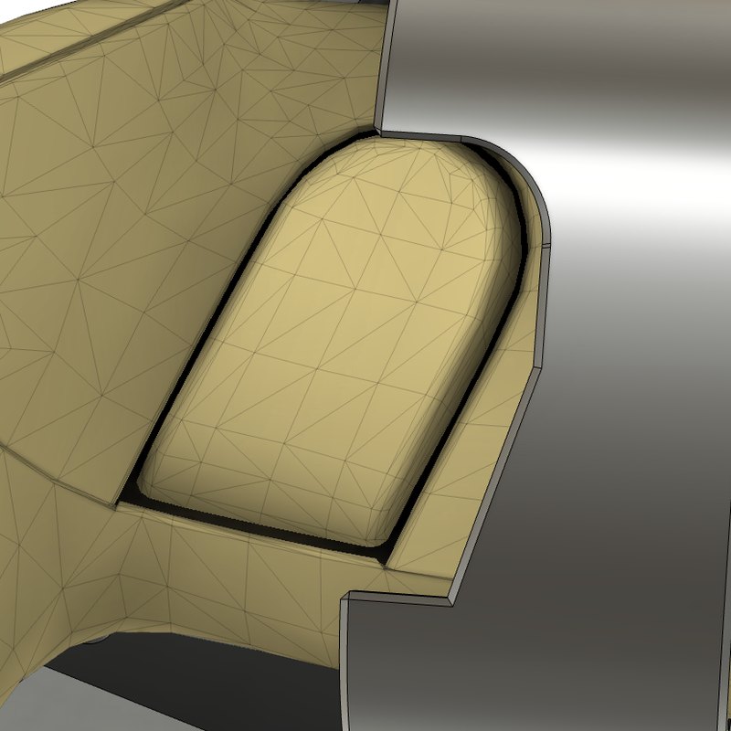
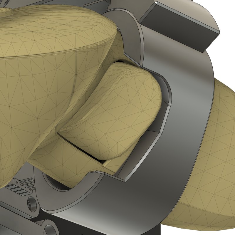
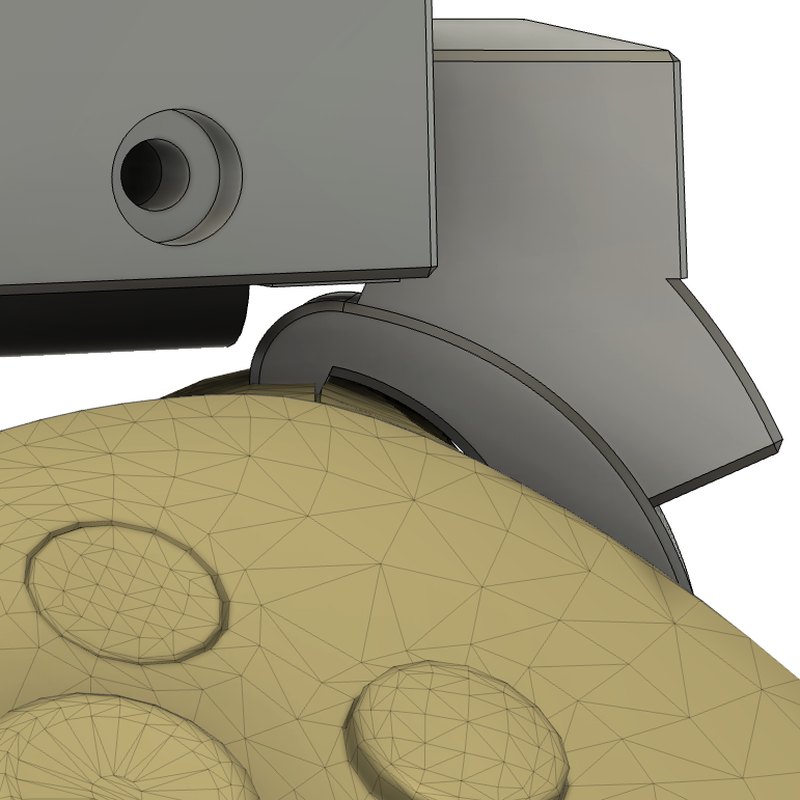
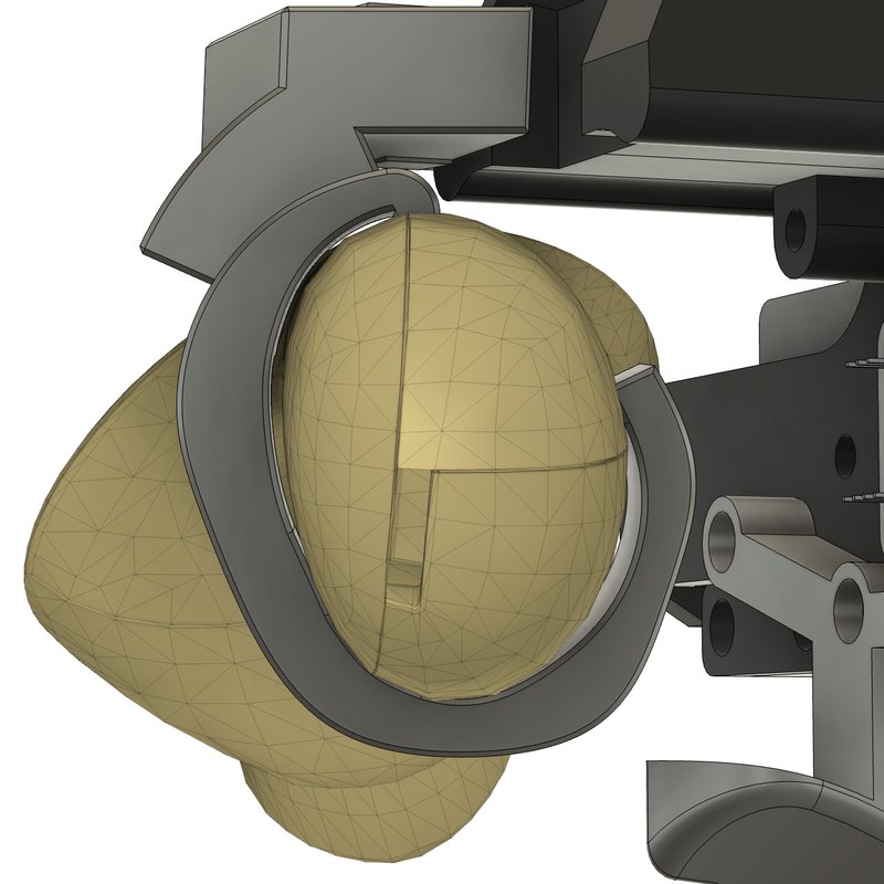
With the help of Claude, you can read out the controller mesh and frame in the Unity SDK and rebuild it in CAD. This allows me to visualize each calibration.
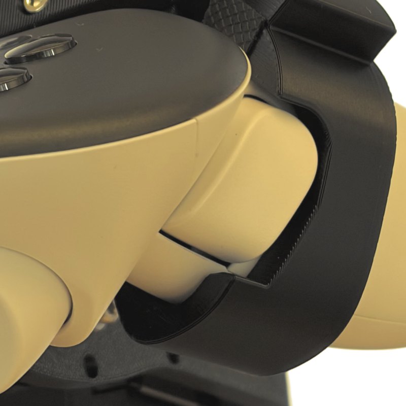
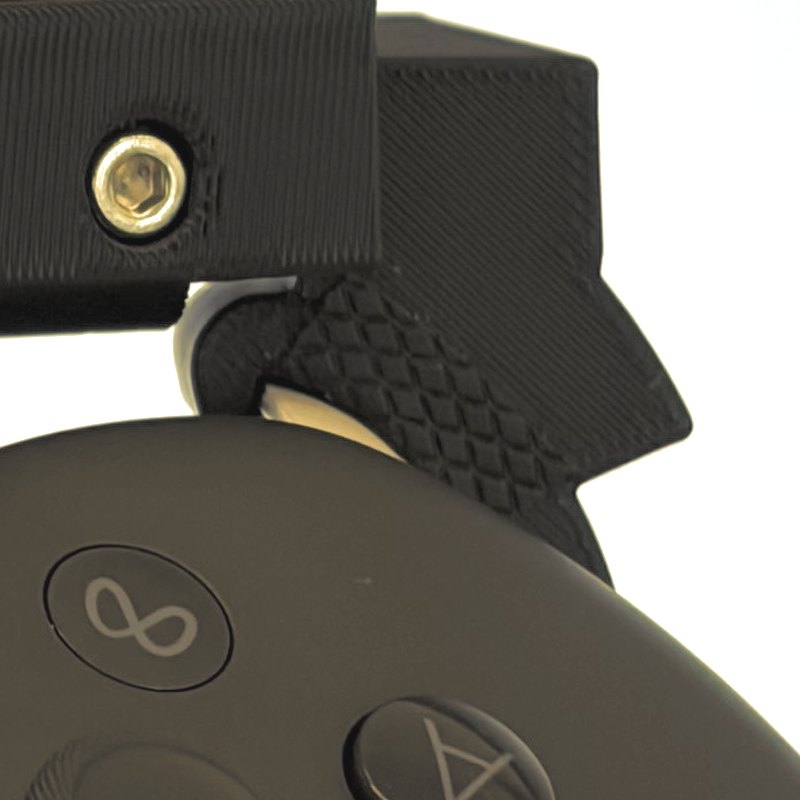
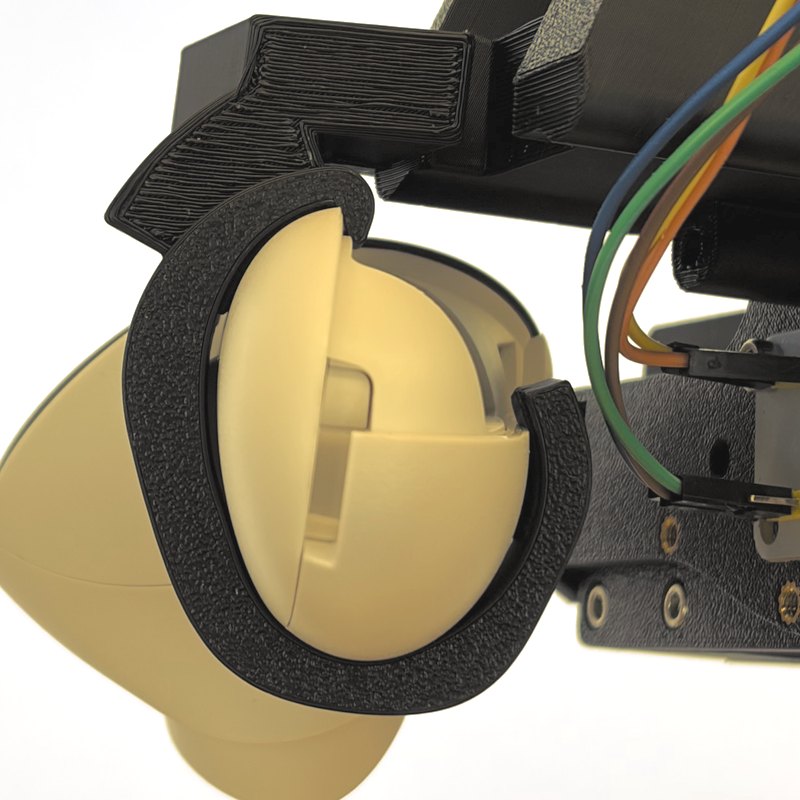
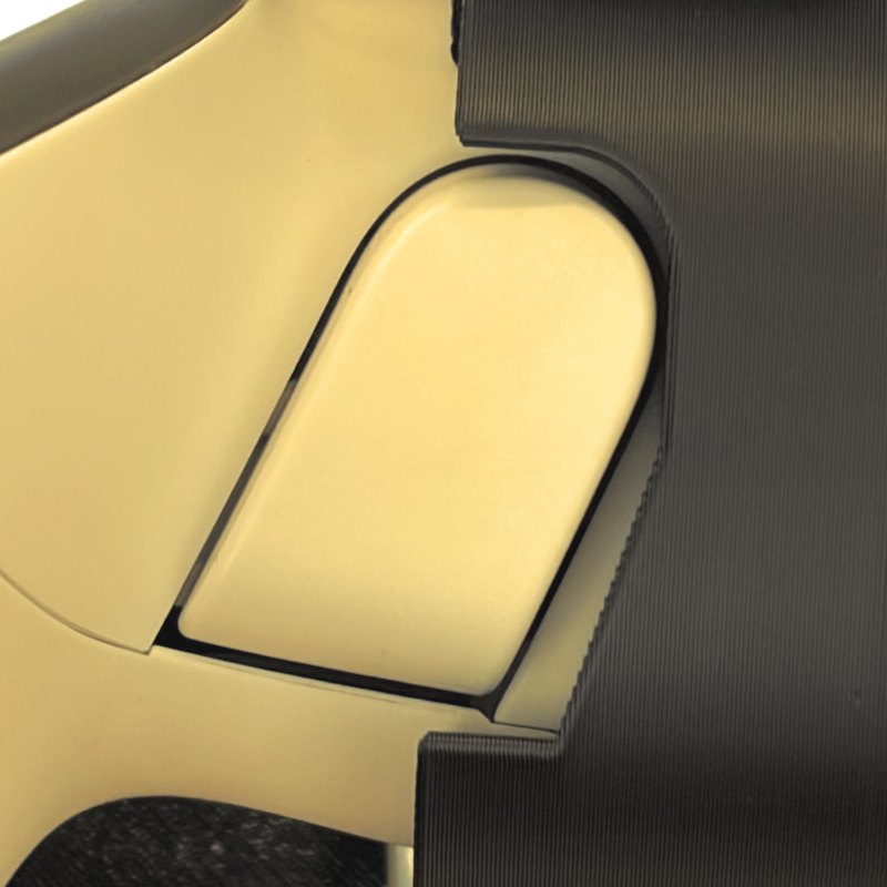
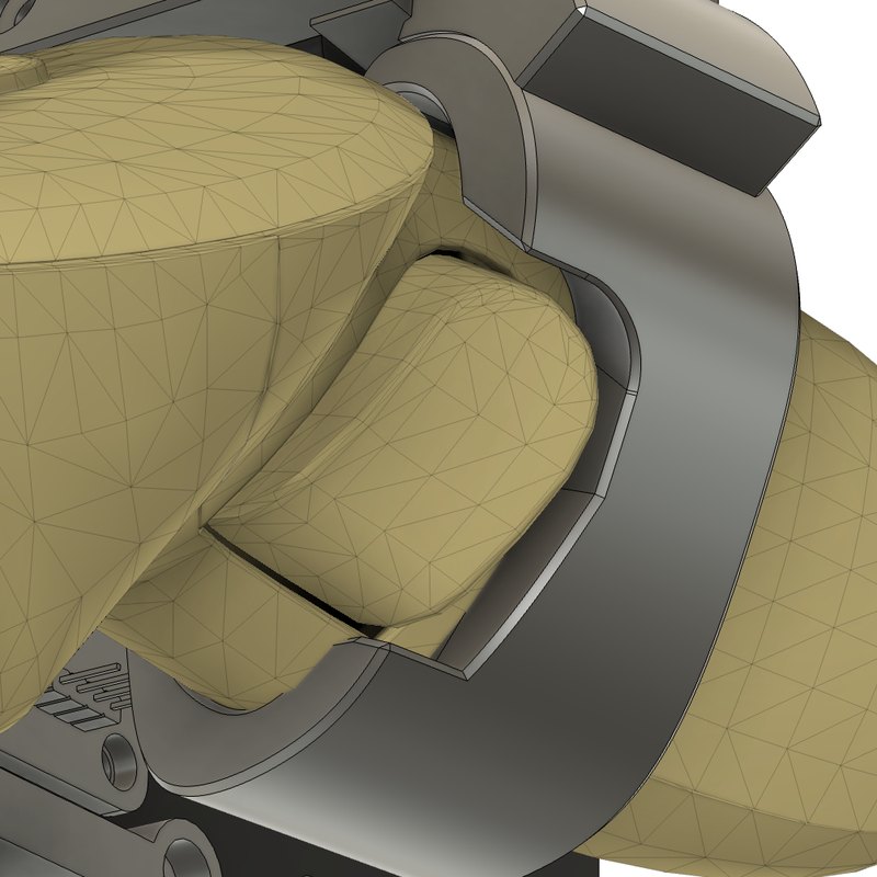
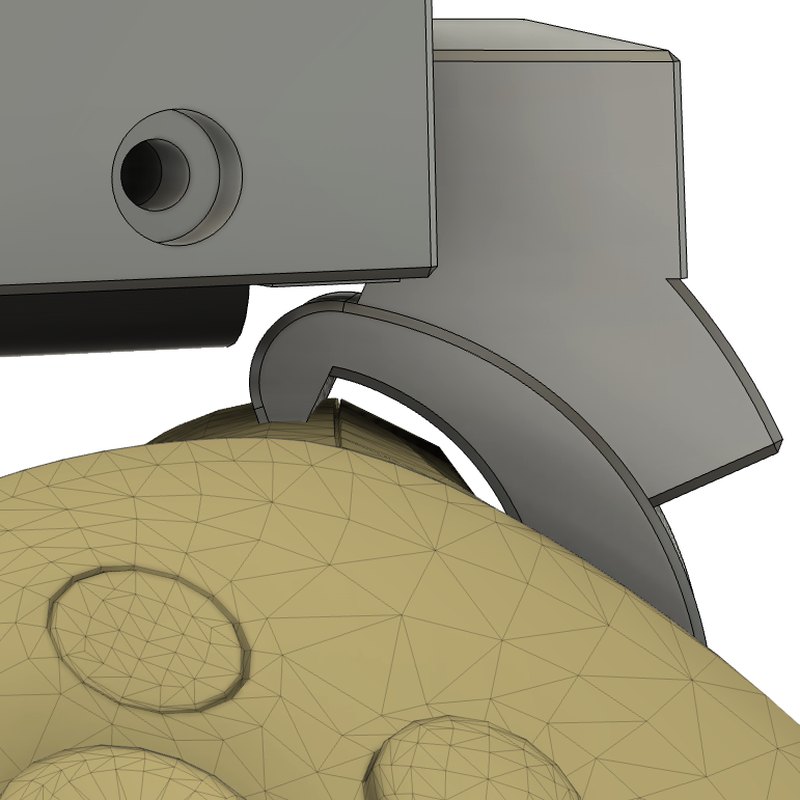
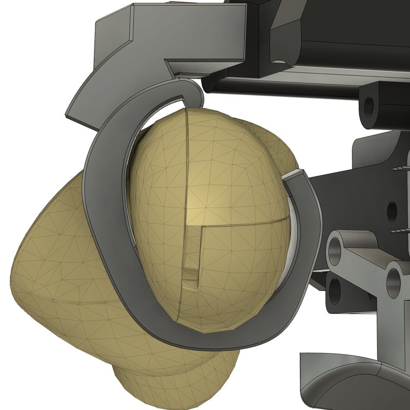
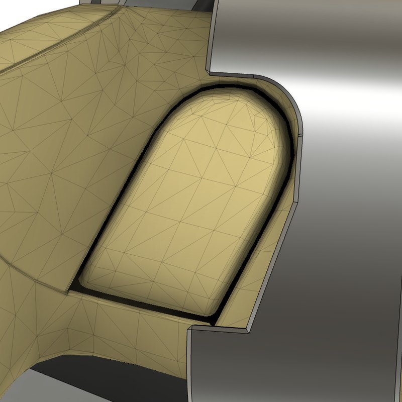
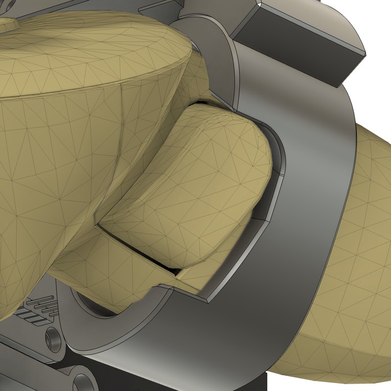
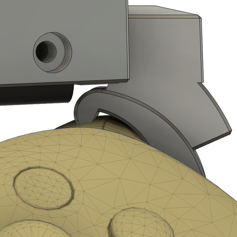
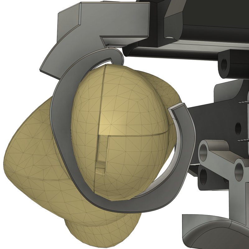
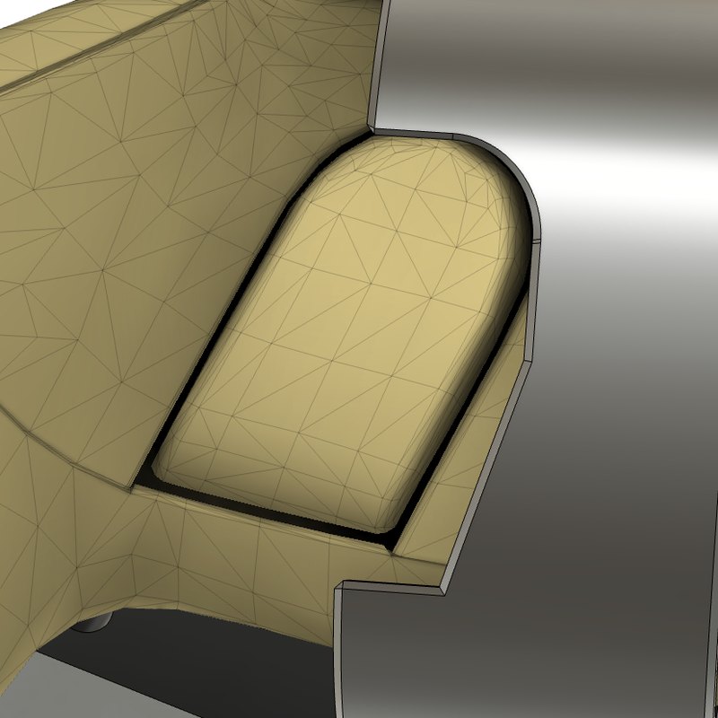
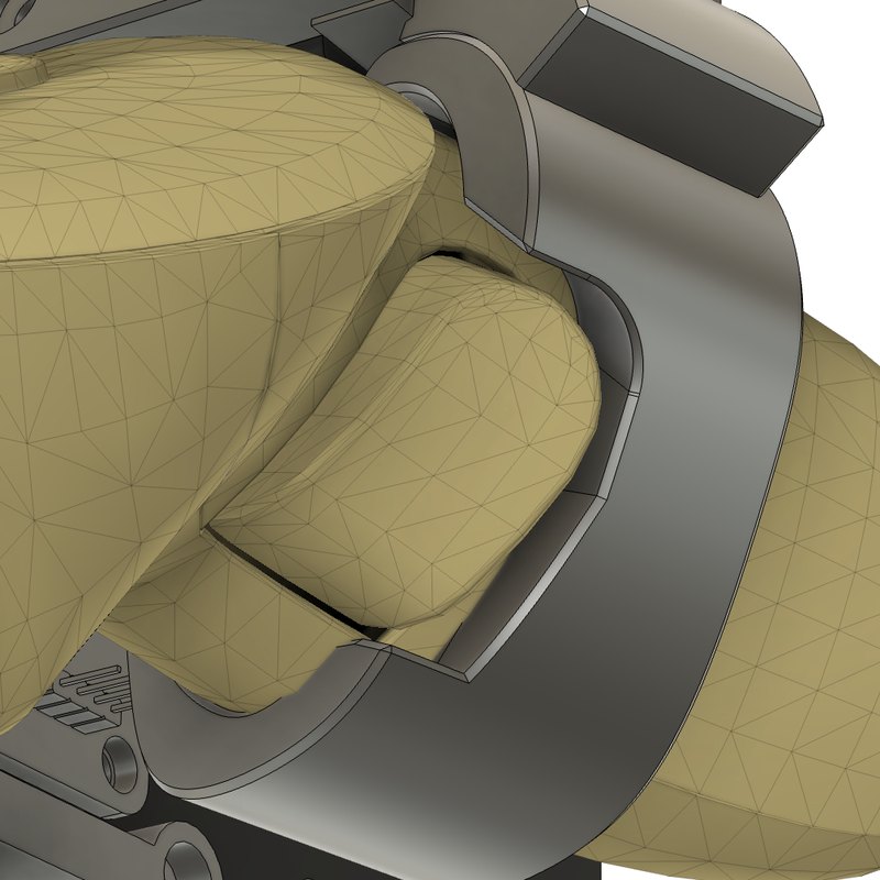
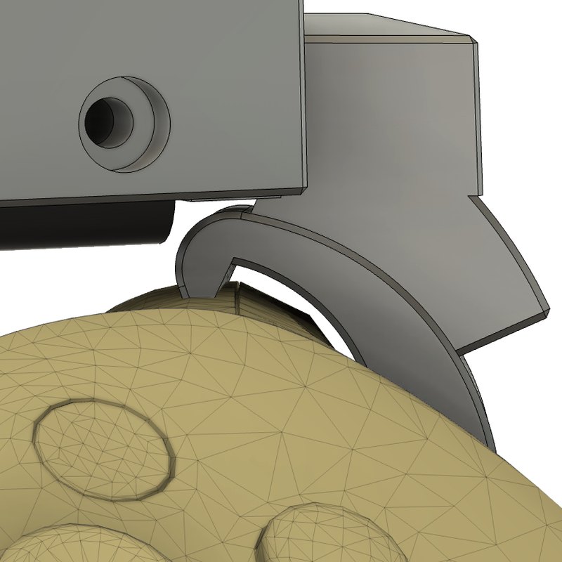
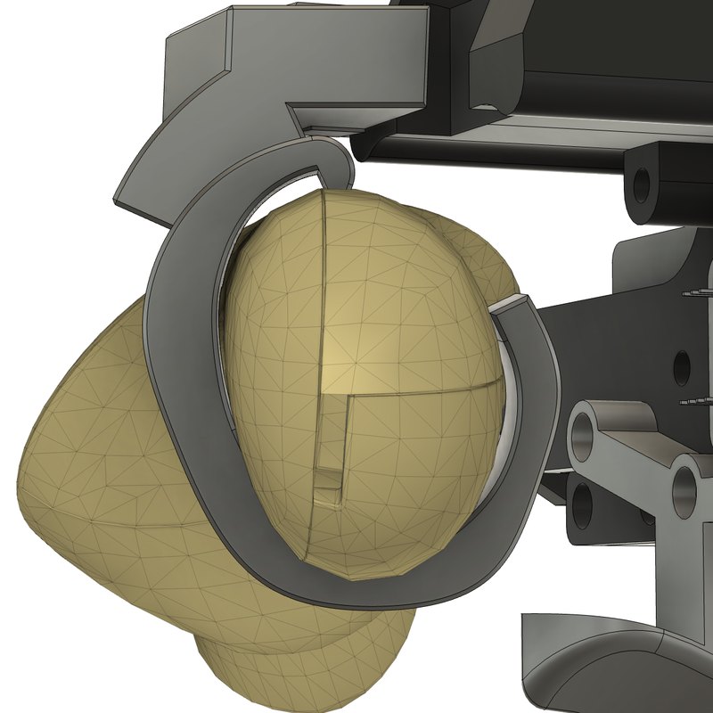
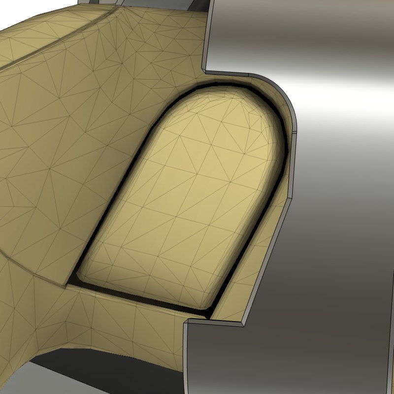
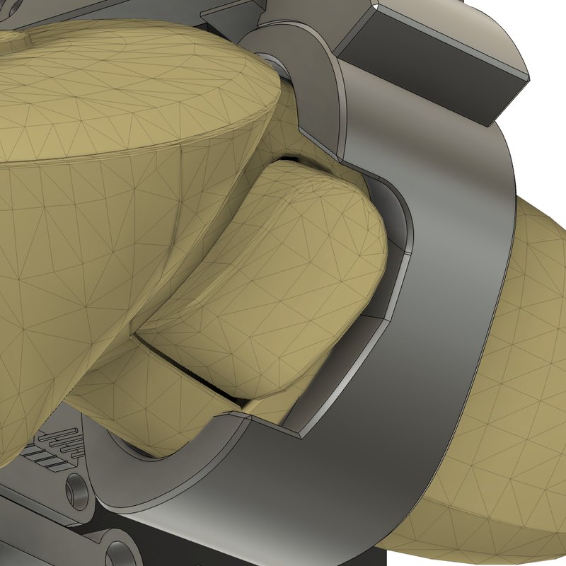
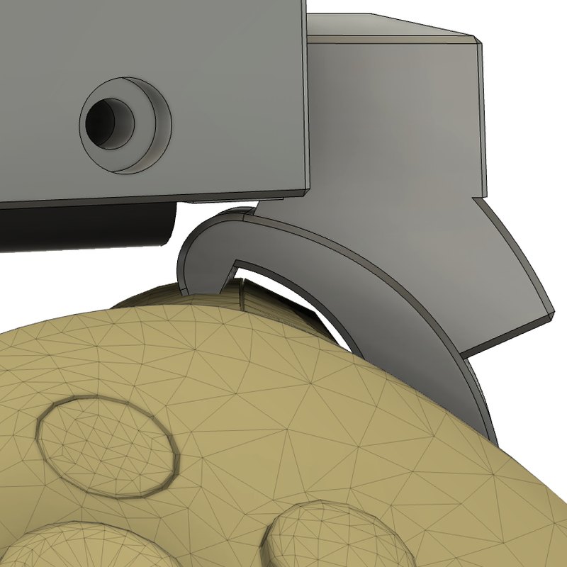
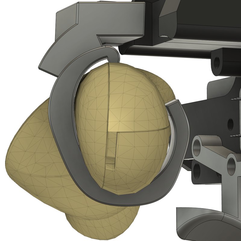
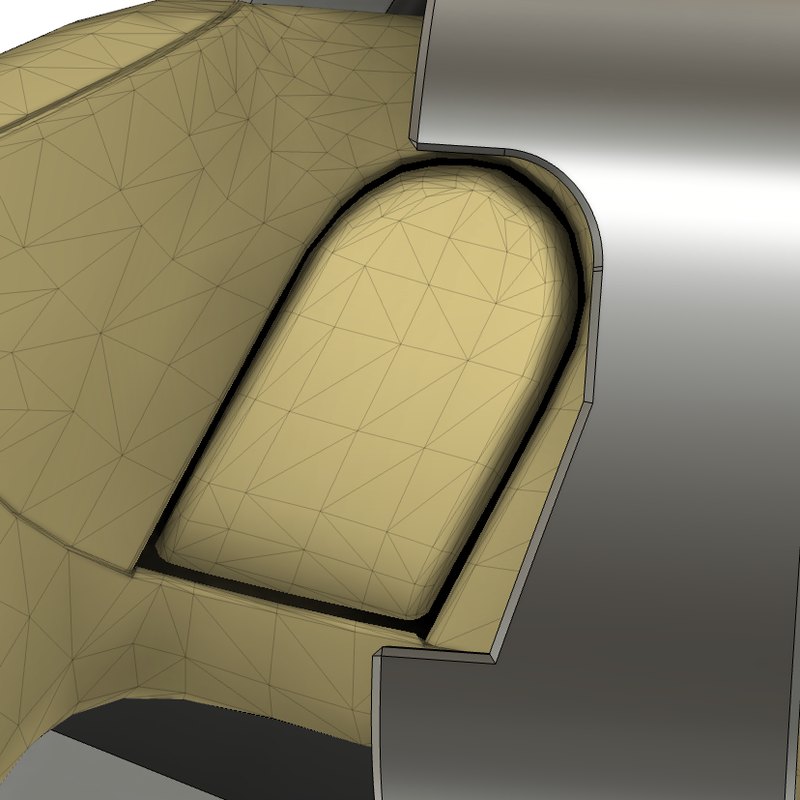
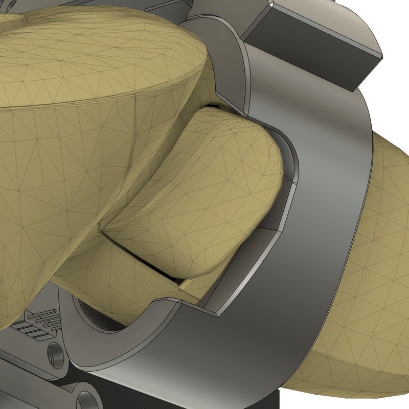
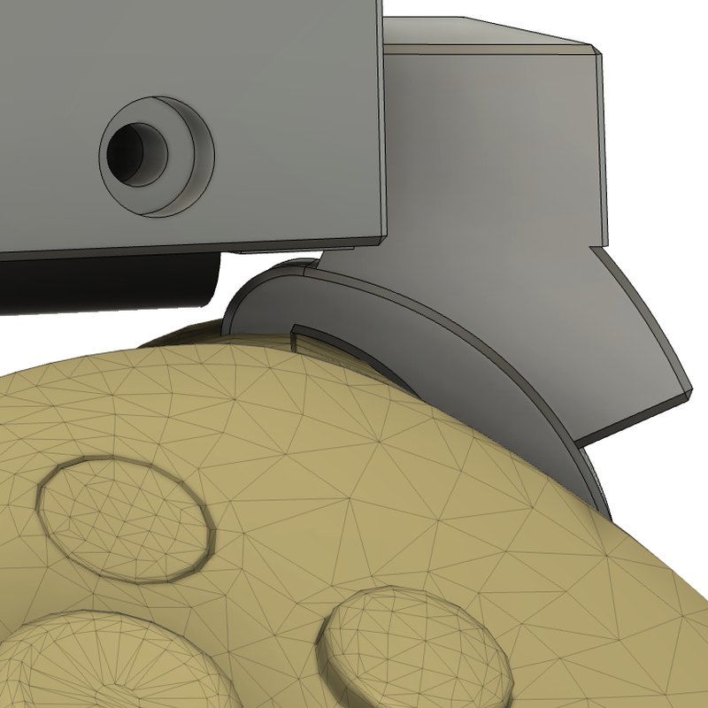
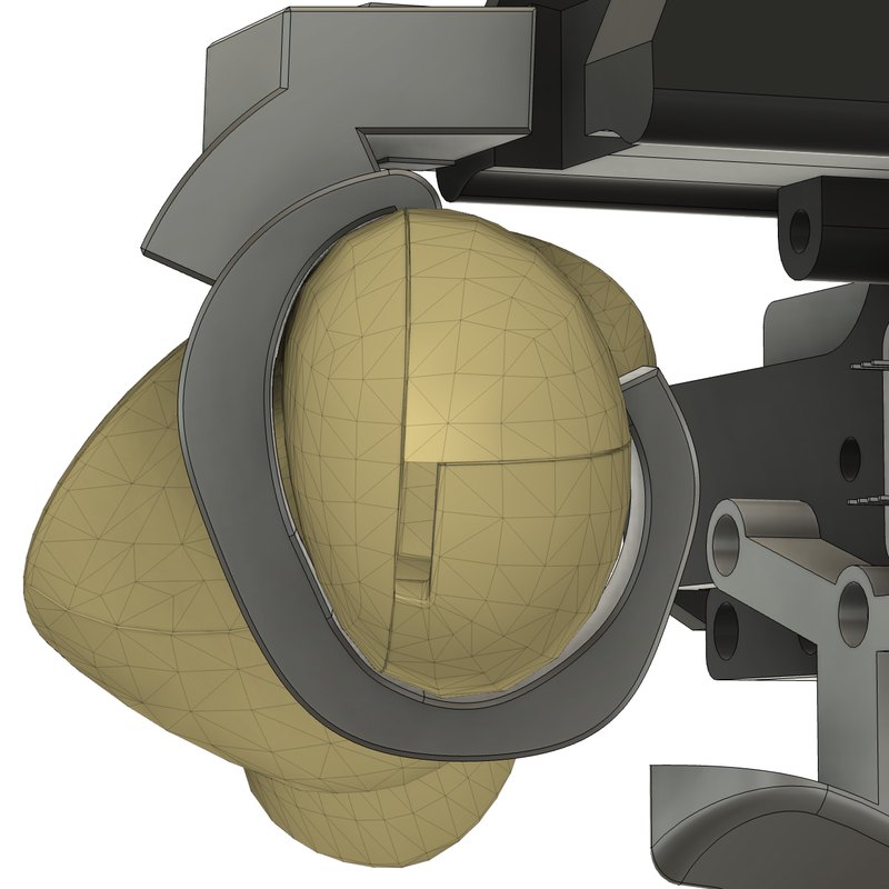
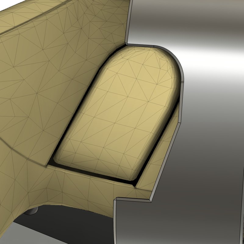
I rendered each calibration from the same four viewpoints as photos of the real controller (Figure 8). Views 1 and 4 show the side button and how it sits in the mount. Views 2 and 3 look along the direction the controller slides into the mount: view 2 at the slit above the controller, view 3 at the whole controller.
These are the same calibrations as in the results above. The first three rows use one method each: ArUco tags on the UMI filmed by the Quest’s own cameras, hand-eye, and a pivot calibration over five points. The last three keep each method’s position but take the rotation from gravity orientation.
No method gets all four views right. The tag-based rows, and hand-eye once gravity sets its rotation, match the side button (views 1 and 4). The pivot rows match the slit and the whole controller (views 2 and 3). Hand-eye on its own matches none.
Since visual results favor no method, I’ll go with the analytical top candidate.
What’s Next
The next milestones will roll out somewhat in parallel. I’ll start by training ACT (Action Chunking with Transformers)13Zhao et al. (2023). Learning Fine-Grained Bimanual Manipulation with Low-Cost Hardware. arXiv:2304.13705. and DP (Diffusion Policy)14Chi et al. (2023). Diffusion Policy: Visuomotor Policy Learning via Action Diffusion. arXiv:2303.04137. on tele-op data to get familiar with imitation learning. Once I have the basics down and a good baseline, I’ll start training UMI policies. While collecting that data, I’ll iteratively build and improve the collection system and its pipeline.
For milestone 2 itself, I plan to:
- Replace my MacBook as the receiver with a portable workstation carried in a backpack.
- Add controls and feedback for the operator during collection.
- Build a post-processing pipeline that makes sure the data is usable and of high quality.
- Measure the UMI’s accuracy further. This could be done with a motion capture system, or with more inventive methods such as recording UMI trajectories, replaying them on the robot and measuring the difference.